NOTE: The most recent updates are at the top.
|
||||||||||||||||||||||||||||
|
||||||||||||||||||||||||||||
|
||||||||||||||||||||||||||||
|
||||||||||||||||||||||||||||
|
||||||||||||||||||||||||||||
|
||||||||||||||||||||||||||||
|
||||||||||||||||||||||||||||
|
[1].jpg)

Specifications
|
More good info:
http://robots.net/article/953.html
 2003/09/30 -
Video (Yes, Video)
2003/09/30 -
Video (Yes, Video)
Don't ask, but I am looking for a USB 2.0 video capture solution to
support 3 cameras.
I have two options:
- Analog Camera through USB 2.0 Video Capture Device
PROs: Small
CONs: Overall, more expensive and more parts- Analog Cameras
-
http://www.microvideo.ca/~microvid/tube.htm
- http://www.aegis-elec.com/products/elmo-un411e.html
- http://www.123securityproducts.com/spapcovica.html
- http://www.aviation-procurement.com/remote-head.html
-
http://www.nctc.com/~dfluehe/cable_cam.GIF
http://www.nctc.com/~dfluehe/LCL_CAM.htm - http://macworld.pricegrabber.com/search_getprod.php/masterid=764719/ut=0441ef23ba3e9c75
-
http://www.microvideo.ca/~microvid/tube.htm
- USB 2.0 Video Capture Devices
- http://www.usb-port.com/uvd201.html
- http://www.usb-ware.com/pinnacle-linx-usb-plus.htm
- http://www.aver.com/products/dvm_AVerDVD_ezMaker_usb.shtml
- http://www.usbmax.com/Category_USB_Video_Capture.cfm
- http://www.pcresource.co.th/html/product/grandtech%20product/Grand%20AV%20USB%202_0.htm
- http://www.usbgear.com/usb-20-video-adapter.html
- Analog Cameras
- USB 2.0 Video/Web Camera
PROs: Cheaper and simpler overall
CONs: Not as small
2003/09/28 - Nano-ITX!
Woot!

- http://www.mini-itx.com/news/computex2003-1/
- http://www.mini-itx.com/#story0245
- http://www.via.com.tw/en/Digital%20Library/PR030924VTF-5_VIAKeynote.jsp
Neat history of ITX:
Oh yeah, in other news...
...I got the USB GPS installed and I am finishing up the installation of the
Xenarc display.
I will post pics when I am done.
2003/09/26 -
Data acquisition ideas
2003/09/25 -
Yet more progress (amazing, isn't it?)
I bought the PanaVise cell-phone mounting bracket. It should be here in a few days.
I received the Xenarc 700TSV USB Touch Screen and USB GPS Mouse Receiver this
week.
I will hopefully install these this weekend, but I will need a 2nd USB Hub;
maybe I can find an
8-port USB Hub?
I doubt it: If you cannot find an item on ebay then it probably does not
exist.
FYI: If you buy the 700TSV, don't be too worried about the cheap ass looking
cable that comes with it. Apparently the heat shrink is normal! :)
I have had the USB GPS and USB Cell-Phone hooked up at the same time with success. I had heard that it was hard to get Microsoft MapPoint to work with some GPS devices. I am using version 2004, and the GPS receiver seems to work fine.
My next purchase will probably be a USB data acquisition board of some sort.
So, the other day I am headed to the doctor and traffic is pretty bad and I realize I am going to be late. It was very cool to be able to bring up the Washington State Department of Transportation's Puget Sound Traffic Conditions web site. Having that information at that particular time was not highly useful (however, it was still useful), but I envisioned a system setup at the house that you can tell your upcoming appointments to, and it can watch the traffic conditions to predict about how long it will take you to reach your destination. You could then use this information to more accurately show up on time. I know, I know: everyone reading this is saying "Just leave earlier!", but that wouldn't be as cool...and traffic is so unpredictable. If I leave earlier, than on some days I may show 30-45 minutes early for an appointment! Ah, I'm just being difficult...and geeky! :)
Anyways, here are the links to the information that I would use if I wanted to write a program to interface with the WADOT's traffic info:
- http://www.wsdot.wa.gov/pugetsoundtraffic/webflow/ - Free Client Software (quite unimpressive)
- http://www.wsdot.wa.gov/pugetsoundtraffic/webflow/datafile.htm - Explains how the client software works
- ftp://webflow.wsdot.wa.gov/ - The source of the client software's data
- http://www.wsdot.wa.gov/pugetsoundtraffic/cameras/ - Freeway Traffic Cameras
2003/09/19 -
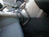
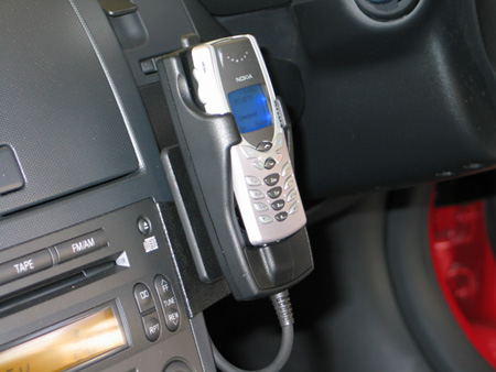
Need cellular mounting bracket
I am looking for a nice way to mount the phone in the car.
Here are some good pointers (you will need an account at
http://www.my350z.com):
-
http://www.my350z.com/forum/showthread.php?threadid=40131

-
http://www.my350z.com/forum/showthread.php?threadid=31398
-
http://www.my350z.com/forum/showthread.php?threadid=28852
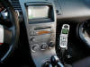
-
http://www.panavise.com/nf/comm/indash/indashviewfinalimage.html?modelID=32608802651538399
http://www.panavise.com/nf/comm/indash/instruction.html?partn=751311003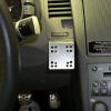


2003/09/19 -
No longer confined to my driveway
I bought the following items in this past week:
- Xenarc 7" USB Touch Screen
- GPS USB receiver
- Sprint PCS Vision plan w/ Unlimited Data
- Sanyo 8100 Cell Phone
- USB/Charging Cable for Sanyo 8100
All of the Sprint/Sanyo stuff came in this week, and damn does it work!
As a test, last night I had an IM session open and was listening to
Digitally Imported all the way home from
work (16 miles).
I did not have a single "hiccup" until I got to my driveway (where I have
bad reception).
The Xenarc screen and GPS receiver should be here next week.
I plan to install the GPS receiver first, so that I can get Navigation
working 100%.
That will give me a day or two to figure out how I want to mount the Xenarc
in to the car.
Once the Navigation is working, I can then remove the existing screen and
put in the new Xenarc screen.
I will leave the GEX in for the time being, and route its video output to
the Xenarc too.
If all goes well I should have this done in a week or two.
I think I could do it in a day or two, but if there is one thing I have
learned it is that these things take longer than expected, so two weeks is
probably more accurate (to work out any kinks).
Once I get the touch-screen working I might be able to install the software
that some guys at work wrote.
And if all of that works well then I might in fact be able to demo my car
with theirs.
Their car is a Chevy Trailblazer:
I think it'd be pretty frickin cool to demo a 350Z there along side it! :)
2003/09/13 -
Cellular Internet
I bought my stuff for cellular internet today.
Before I bought I checked out the boards at http://www.mp3car.com and http://www.3gupload.com
Here is what I got:
- Sprint PCS Vision
- $60/mo (replaces my current $35/mo AT&T cell, so it costs me $25/mo more than I am used to...still expensive, but no biggie)
- 500 anytime minutes
- unlimited nights/weekend
- unlimited PCS vision (as long as it is not abused)
- 2 months free "premium pack" + $15 trial credit
- 50 minutes home long distance free
- Sanyo 8100 Phone ($100: $230 - $130 automatic rebate)
- USB/Charging Cable for Sanyo 8100
NOTE: You will specifically want to buy a combo data and charging cable - Sanyo 8100 7-piece accessory kit ($26 on
http://www.ebay.com)
- USB Data Cable
- Li-Ion Extended Battery
- Rapid Car Charger
- Travel Charger
- Hands-Free Headset
- Belt Clip #2
- Universal Phone Holder
- Download Sprint software from their customer site
These phones say they are capable of 153kbps, or 19Kb/s; not very impressive, but it should be good enough for my current plans (signaling, instant messaging, light-weight web, single session audio and/or video)
2003/09/12 -
This page is due for a journal update!
Wow! It's been over a month since my last post. I have been enjoying doing NOTHING related to the car except enjoying it (and answering a few emails). I also got a few things in my life in order (aka: new job). Alas, this page is not a "Diary", so I'll avoid any discussions about personal matters.
Despite the stagnation of this page, quite a bit has happened, especially in the past week. I have found 3 guys where I work that have had PHENOMENAL success in writing a Windows XP shell for an automobile. I met with them on Friday and saw their product...VERY NICE! There are some bureaucratic things that they need to get through before they can consider giving me access to their binaries or source code, but if everything works out this would save a TON of time in writing what I wanted to for the car.
So, for now, the shell and UI areas are WELL covered...allowing me to focus on the nitch areas of the software that I want to work on.
- Cellular Internet - will order tomorrow
- File Replication/Mirroring (to/from Car) - more than half done
- Display Windows Media Player VIZ - need to see the x-car source code
- OBD-II
- WiFi WarDriving - need GPS device; more than half done in C#, nearly 100% done in C++
- Radar WarDriving - needs EE to interface w/ radar, but uses the same basic software as the WiFi WarDriving
- "Parking Lot" idea - needs some thought before anything else is going to happen...
More OBD-II info I stumbled across:
http://www.mymp3car.com/MP3Car/mp3carfaq.asp#useful_info_obdii
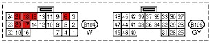
Here is the ODB-II connector in the 350Z: (why is Pin 15 missing?)
| ISO 9141-2 w/ CAN |
|---|
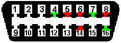 |
| Pin 4 - Chassis Ground Pin 5 - Signal Ground Pin 6 - CAN High (J-2284) Pin 7 - ISO 9141-2 K Line Pin 14 - CAN Low (J-2284) Pin 15 - ISO 9141-2 L Line (!missing!) Pin 16 - Battery Power (+12V) |
Finally, I got my [disappointing] review back from work. It was not anything near what it should have been (yet another reason I am leaving the group), but it is sufficient to inject a bit more cash in to my project. I get paid on 9/15, and I will pay off the cards and start building up a balance again. My first few purchases will be:
- Xenarc 700TSV 7" USB Touch-Screen VGA monitor
- USB GPS receiver
- Cellular Phone w/ Internet capabilities
- 54G WiFi (aka: 802.11g)
- Base Station
- USB Adapter
I am beginning to realize that I should perhaps turn this journal in to a BLOG and provide RSS feeds...but that would assume that people are reading this and actually care. :)
2003/08/08 -
Wireless! Well, WiFi at least!
I bought the Microsoft Wireless Desktop Kit yesterday for $100. I've heard bad things about it, but the price was right, and if I run in to any problems I will just send it back. First thing I do is plug it in to The Z and I start to pick up the occasional HotSpot. I still need to figure out how to access these for free, but they are so sparse that I only really care about the ones at my house and at my work, and I spent yesterday solving that. The connection to my home network was easy. The connection to my work network was a small pain. To get WiFi from my corpnet I needed to install a security certificate in the CarPC. I did not want to physically take the computer out of the car to do this. My solution was to drive to work to get my SmartCard reader, drive back home and use my WiFi network at home to VPN in to work (which requires a SmartCard), add the CarPC to the domain, reboot, re-VPN in, request a machine and a user cert (apparently I needed both), and then remove the CarPC from the domain. The VPN connection over WiFi was a little slow, I think that was only because it was a "first time" connection and they needed to do some security checks and I also installed their anti-virus software. I made a 2nd VPN attempt and it went much faster. I then drove back to work and tested out my WiFi access. It was hard to find a parking spot with a decent signal, but I did. The first few connections were VERY slow, and authentication sometimes took several minutes, even with a "Very Good" signal strength! Here too there were apparently a lot of "first time" bottlenecks, but after a few connections things started to speed up. I can pull in to work now and be automatically connected in less than 30 seconds, which is acceptable.
One pain with this setup is that I need to turn on Proxy Settings if I am on corpnet, otherwise I need to turn them off. I need a little script or utility that automatically does this.
Having the ability to wirelessly access both Work and Home is pretty convenient. I can do my main tasks on these two hard-points, and then download the stuff I need to the CarPC when I start it up.
First thing I need to do now is get "the other half" of my MP3 collection off of the CarPC and on to my main desktop machine so that I can finish organizing the files a bit more.
After that is done I need a setup where, when I turn on The Z, it queries my desktop machine to see if there is anything waiting on it:
- Shopping/TODO list
- MP3s
- Data/Spreadsheets
- Command to "Upload" files from The Z to my desktop.
- etc.
- Work (what the hell is that?)
This will probably involve using the "Briefcase" feature of Windows XP, which is suiting because I call The Z my briefcase anyway (the trunk is barely useful for holding anything other than what you could fit in a briefcase). The other built in option is to use Offline Folders. These can be synced at Log On, at Log Off, at Idle, or at scheduled times. I don't know how this will work on a PC that goes in to "Hibernate" mode. I think the Briefcase would be more useful.
I have also thought about some sort of replication/mirroring process that takes place when I start up the CarPC (ie: pseudo backup of the home PC), but this is not very practical with only a 40GB hard drive in the car. It will barely hold all of my MP3s! So, I think the other idea of preparing files on my desktop and auto-retrieving them when I start the car is a better idea.
2003/08/05 -
Organizing my next plan of attack
| Item | Proposed Solution | Price | Cons |
| 7" VGA Screen | Xenarc 700 TSV (USB Touch) | $499.00 | Need to custom mount |
| GPS Nav Software | DeLorme Earthmate/Street-Atlas | $129.95 | Cheap, and few voice commands |
| 802.11 Base Station | Microsoft Wireless Base Station | $60.00 | Range? |
| 802.11 Device | Microsoft Wireless USB Adapter | $40.00 | Range? |
| Wireless Internet | Verizon Express Network | $35/mo-$79/mo (replaces cell phone) |
40-60kbps average |
| OBDII Software | AutoTap -or- ScanTool |
$289.95 - $85 - $115 |
I don't know if it is any good - Write my own software |
- OBDII Links:
2003/08/02 -
Speech
So, at the top of my list of things to change is the LCD screen and some decent Navigation software. Those are things that I can fix now, and would help me for v2.0 the future. However, I already know the solution for these two areas, so they don't grab my real interest.
My real interests are:
- Speech Recognition
- Artist/Track/etc info displayed in WMP9 full-screen mode
I think this will involve writing my own MP3 player that uses the WMP9 ActiveX control - Designing v2.0:
(CONCEPT ONLY: the keypads will change a bit and may not fit as intended)
Replacing the Bose head unit with the black version of this 2DIN version will solve nearly all of my current gripes.
2DIN stereos are typically 7" W x 4" H x 6.5" D.
The C138 is 7.99" W x 4.1" H x 8.17" D.
The Z has about 7.5" W x 4.5" H x 8.5" D, so something will have to be done with its width.
The Speech Recognition intrigues me a lot! The GyroMouse and Keyboard are more than sufficient as input, but they are a bit awkward. I'd like to get to the point where I can just say "Next", "Volume Up", etc and not have to touch a thing (maybe a "key" on a mic). That is a bit sci-fi, but I think it is doable with certain limitations. Ideally I could also delete and arrange songs on demand. "Techno" would only play that genre. "Rock", "AC/DC", etc. I should just be able to say info about a song or set of songs and those songs will play. I could possibly even build a playlist vocally; "Add this song to the current playlist". I could ask the computer the Artist info and it would tell it to me. I could verbally rank songs using the built in WMP9 rating system, and then verbally request "4 star [and above] songs". Very cool possibilities, and I vaguely understand the limitations of speech technology, but part of the challenge is to bend or reduce these limitations.
2003/08/01 -
Seriously...
...I am considering what I would want to do for a v2.0 of my car's PC.
So I've had several days now to play with the PC in the car. Everything is working pretty well. There are a few kinks still left to be worked out, and things are a little rough around the edges, but all in all the system works, and that is presently what is most important.
- Power
- Startup
- Sometimes I have to turn the engine on in order for the PC to turn on.
- The GEX, the PC, and the Screen sometimes don't sync up
right during startup (I estimate less than 5% of the time).
The result is that the VTR1 input never stabilizes on a sync signal, and thus no useful picture can be seen.
I haven't looked in to the problem yet, but I suspect the problem is that sometimes the GEX starts up before the PC and cannot find the PC's video signal and thus lets the VTR1 input scroll out of control.
When it happens it is a pain to reset; I have to shut everything down and start it back up.
- Shutdown
- The ATX shutdown does not know/care if the computer is on or not.
If the computer is manually turned off before the ignition, the ATX pulse will still occur, thus turning the computer ON.
This rarely happens, and is simple to correct whenever it does, but it is still a small flaw.
- The ATX shutdown does not know/care if the computer is on or not.
- Startup
- Screen
- The Nav's LCD screen makes it hard to read fonts on the screen.
It needs to be replaced by a VGA screen, possible even a touch screen.
Surprisingly, touch screens in a car are supposedly inconvenient.
Removing the built in Nav's LCD screen will pretty much render the GEX and built in Nav system useless.
- The Nav's LCD screen makes it hard to read fonts on the screen.
- Keyboard/Mouse Input
- The keyboard is fine, although a bit cramped like a laptop.
I would much rather prefer a full-sized keyboard, although I should try putting one in my lap to see how comfortable it is. - The GyroMouse takes a LOT of getting used to.
It is VERY cool, but I may never get used to it. :(
Keep an eye open for other better input devices.
- The keyboard is fine, although a bit cramped like a laptop.
- Audio
- The FM modulator sucks!
There is noticeable static when the system is making no sound.
There is noticeable "wow" and hum in the sound.
Still, the sound is decent, and much better than any FM radio station. - I should eventually replace the Bose stereo head unit.
Another option is to work on my NavPC v2.0 below, which would replace Nav, PC, and Bose. - I wish Windows Media Player 9 would display the Artist/Title/etc
info when in full screen mode.
I would not mind having the info always displayed on the screen, but an adjustable timer would be best.
- The FM modulator sucks!
- General
- Look in to an 802.11 connection (for needing files at work).
It is fairly inconvenient to take the PC out of the car whenever it needs an update that is too large to fit on a CD. - Look in to good GPS software (since we may be losing the existing Nav screen [and thus system] anyway).
- Look in to a wireless internet connection.
- Look in to putting touch pad in the coin tray spot.
This was an idea that I got from a guy on one of the boards I frequent. - Look in to voice activated commands.
- Look in to an 802.11 connection (for needing files at work).
2003/07/31 -
Ah jeah!
NavPC v2.0
+
![]()
(A keypad close to what I am looking for)
Enough said! :)
2003/07/29 -
Just got the computer back, made improvements in the meantime
So I *JUST* got my computer back from leaving it in Tennessee. Actually, I have the UPS claim tag for the package; I still don't have the actual PC back in my hands yet! I will pick it up tomorrow and drop it back in the car sometime this week. I may delay another day or two while I take it in to work and update it with Microsoft Street and Trips 2004. As soon as it is back in the car I take pictures and post them here.
I took this past week (or two) to work on something that has been bugging me. With the current wiring, when you turn off the car you also turn off the screen (as Nissan has intended). This means that you cannot see progress of the PC while it shuts down. What if there were a problem during the shutdown? Wouldn't you like to at least see that something went wrong (even if the timer kills all power eventually anyway)? Wouldn't you like to see the nifty "hibernating" splash screen? (it would be rather cool to step out of your car and lock the door and see a "shutting down" bitmap on the screen) :) It makes sense to keep the screen powered on until after the PC has finished shutting down. This is fairly easy to do with the ATX Shutdown Circuit.
The power wiring was a bit iffy anyway, so I took the opportunity to fix both the iffy wiring and the screen shutdown problem. The screen problem was easily solvable by changing the display's "Power On" signal (Pin #19 [Light Green]) from using the car's "ACC" voltage to using the delayed voltage from the ATX shutdown circuit instead. The trick worked, and now the screen stays on as long as the 12V DCDC converter. I can confirm this by viewing it at night; the screen is backlit for a good minute or two after turning off the car. However, the GEX seems to think that something is missing from the equation, so it goes ahead and stops sending video the moment the ignition is turned off (ie: the screen goes black). I suspect it may be because the Nav unit itself does turn off immediately with the car. The GEX probably sees the absence of the Nav device and stops sending video to the screen. This doesn't make much sense to me; I think I am sending the proper delayed voltage to all the right components. I will see if I have missed anything and will be playing with this over the next few days. I should be able to confirm a lot by seeing what happens to the GEX when the Nav unit is simply unplugged. If the identical thing happens ("the screen goes black") then I suspect I will also have to delay the Nav unit's power off until after the PC's shutdown. This will be very easy to do (same trick I used for the screen), I just want to know if it is necessary. As always, more info to come...
FYI: I plan to draft up an image of the wiring schematic once I know everything is working tip-top.
2003/07/12 -
Got things working now that I am back from July 4th vacation
I just got back from July 4th vacation the other day. After a nice break I am ready to finish this thing up once and for all (honestly, I am getting a little tired of it). The break was well needed, and the timing was good because I was waiting on my EL4583 chips to come in anyway. When I got back I got a burr up my ass to build a new version of the IR/OSD circuit that does not use a 12V input. I designed it and built it in one night, and you can see the results on the GEX page. I tested the circuit this weekend and it is the best working circuit that I have built so far, so I am going to stick with this one for awhile.
So, basically the GEX is working, meaning that the Navigation and TV tuner show up on the screen and have a pretty good quality. I can fairly easily bypass the GEX by pulling a few plugs, and I when I enable the GEX I can definitely detect a tiny degradation in video quality. It is not enough to be concerned about at the moment; I'm just happy that it works at all! The remote control took a little bit of getting used to, especially to set it up the first time. What I am mostly disappointed in is the quality of the TV reception. When driving the car the video quality turns to shit. I can't blame it...imagine watching TV while having the rabbit-ears moving around all of the time. So, I'll try to find some solution. I don't think it has anything to do with my IR/OSD circuit. The Navigation has no distortion, and if there was something wrong with the IR/OSD I would expect the Navigation to be distorted too. I think is a problem with the GEX TV tuner itself. Perhaps a magnetic choke on the power supply is all that is necessary. Also, when I set the audio source to TV, my FM radio reception goes to shit. This is not a huge deal, because I won't necessarily be listening to the radio at the same time I am watching TV. However, I do have to purposely unselect the TV audio source before I can listen to the radio. That is a tad bit annoying.
I also did something stupid while on vacation. I took my Travla computer to Tennessee with me...and I left it there!!! My Ma' is gonna have to mail it back to me. Oh well, I know everything works now. The video was the final hurdle, and it is solved now, so the physical act of putting the computer in the car is kind of anti-climactic.
I have no idea
what I am going to do with my free time now that everything is [hopefully] solved.
Ah, I am sure I'll think of something...maybe I'll go pick up some chicks!
:)
2003/06/28 -
Houston, we have lift off!
WOOT! It has been almost exactly 3 months since I started this project. I can happily say that, with one [not quite so minor] exception, the entire computer system is fully operational and works like a champ. The timing of everything arriving was perfect! The Switched Mode power supply is fucking sweet! Jeff Mucha's ATX Shutdown controller is a life saver! The TV antennas are wired up to the GEX and ready to go. However, the "not quite so minor" exception is that my video sync strip circuit for the GEX is not 100% operational yet. So, I have no video. I am driving around with a PC in my car that I cannot see the video on. I AM SUCH A GEEK! :)
I hooked up only the "RGBS through" cables last week and instantly noticed poor/fuzzy video quality on the screen. The video quality was totally unacceptable, and I stayed up late that night working in my car trying to understand this. To troubleshoot this I built just a simple 6" RGBS jumper cable made out of some of the same VGA video cable that is already carrying the RGBS signals. I soldered the ends of the wires to a male and a female HD15 and spliced this cable in to the wiring. The same shitty video quality occurred. So, I made a second jumper cable and put it in a shielded box and the video quality was good again. I took the new jumper cable out of the shielded enclosure and the video quality remained good. So, I ended up more confused than when I started.
All is good because anyways I did not like the existing video circuit that uses the LM1881 chip. That chip does not output "Horizontal Sync", and output "Back Porch" instead. I hear this causes the screen to shift about 1/2" to the right when the OSD is in use. So, I came up with a new circuit using a much better video sync chip that outputs true HSYNC. When I build this new circuit (this coming weekend) I will try to incorporate what I have learned from the problem of the poor video quality. While the new circuit is being built I will be using the old circuit and just treat it's shitty video quality as an incentive for me to complete the new circuit ASAP.
Photos of the entire system in operation will be coming fairly soon!
2003/06/22 -
RGBS Video Cable v3.0
I just got done wiring the RGBS video cable to the 3rd time. I am just a fucking anal perfectionist! On each of the previous 2 wirings there was something that was not perfect and was bugging me. I actually did have a valid reason to rewire the cable each time, so that helped me to produce what I feel is a perfect result this 3rd time around.
The first wiring was gay, literally, because it used male VGA connectors on both ends of the cable. This was just fucking stupid on my part! How in the hell am I supposed to connect them together if the GEX is not there?!?! To top that off, I could not use a simple gender changer because the pinouts would then be reversed! Believe it or not I actually wired a gender changer that reversed the wires circuit (thus lining the back up 1 to 1). I am such a dumb-fuck! :)
The second wiring used a male to female cable, but it was of poorer quality and did not have ferrite chokes on it. I also soon learned that the GEX needs a 12V input on the "From NAV" connector in order for it to send the NAV's signal to the "To Display" connector.
The third wiring used male to female connectors on the original high quality cable, and gave me a chance to send 12V down the line so that I could pump it straight in to the GEX.
I learned little tips and tricks and shortcuts each time I wired up the cables. I've tried to put these steps in my video cable wiring guide, so I advise that you at least read through my steps so that you can learn from my mistakes and do an even better job yourself.
The quality of your video wiring job is very important, so do not skimp on it!
2003/06/11 -
Power Supply
After several months I have finally decided on the power supply solution. It's going to end up costing me about $130, but at this point I do not care anymore! :) I refuse to use a DC to AC inverter, even if it is a "cheaper" solution. It is senseless and inefficient to convert 14VDC to 120VAC and then back down to 12VDC.
The solution is a link that I have had for many months now and was ignoring because I thought I could find a better solution:
I wrote them an email for an order and they were very prompt with a reply, and even questioned my application and addressed some concerns that they had with my possibly overloading the 5.5mm connector. They seem like an AWESOME company! I think my power supply solution is in good hands with them!
2003/06/10 -
VGA cables
The video wiring is [mostly] in. As the directions in my GEX-P7000TV page indicate, I have tapped in to the Nav system wiring with the ends of a VGA extension cable that I cut in half. I can easily pop everything out and connect the male and female ends together and effectively return the Nav wiring back to its original state The VGA cable/connector is a little overkill, but it's damn high quality! I should not have any problem with video noise from these wires. I have also modified the GEX wiring with VGA connectors so that it can easily tap in to this new wiring. This should allow me to more easily experiment with other video devices if I want to.
My next tasks, in order, will be:
- Finish the VGA ends on the GEX RGB cables
(jumping the orange and white wires is the only thing I haven't solved) - Wire in the power harness for the GEX
- Find a better IR eye than the kind of awkward RadioShack one
- Decide on whether to build the IR/OSD circuit internal to the GEX, or external
- Build the IR/OSD circuit
- Complete the GEX install
- Finish wiring Jeff Mucha's ATX Shutdown Controller
- Make the shutdown jumper wire and install it in the computer case
- Install the Shutdown Controller
- Come up with the final mounting solution for the computer in the car
- Power everything up with a crappy inverter for now
- Solve the regulated 12V5A power supply problem (removing the crappy inverter)
2003/06/08 -
3rd time is a charm!
Well, I am at my 3rd generation version of putting this video navigation system wiring together. As I hope I made obvious towards the beginning of this journey, my solutions were experimental and did not follow similar CarPC solutions. I thought I could piece together my own solution based on the experience of others. Well, I am a dumbfuck, so I am ending up with a solution like all of the other out there. Hey, I tried!
I don't like this solution for 2 reasons:
- It requires me to buy a $240 part
- It uses the composite video output of the computer, and not the VGA output (the obvious best picture quality).
The solution looks identical to http://www.video-nav.com/, but with half the price tag. I got almost all of my ideas from the following sites:
- http://www.acura-tl.com/forum/showthread.php?s=&threadid=51326
- http://mywebpages.comcast.net/boom3/
- http://www.acurainspired.com/albums/album60/aat.sized.jpg
- http://www.geocities.com/wonderer369/G35Nav.html
- You might see a reference to a guy making internal modifications to
the GEX-P7000TV:
http://www.imagestation.com/album/?id=4290461187
I do NOT recommend this!
The "cleanness" of this internal solution does not justify opening your GEX and voiding its warranty.
2003/05/20 -
Back to the drawing board
I've made quite a bit of progress in the car's navigation system, but I am taking things pretty slow.
The DA1910 and DA1914 devices are all hooked up and working. This morning I plugged in my computer to the system and tried it out. As a feared, the fact that the DA1910 is not a true Scan Converter is going to be a problem.
I will most likely have to try another solution for the video connections. I found this very useful site: http://www.video-nav.com/
2003/05/04 -
Final wiring plan is made
I think I have finally determined how/where I am going to run the wires for this project. The determining factor was figuring out where I was going to put the PC. With that finalized (see the computer section) the wiring problem sort of solves itself. The computer will be located basically right next to the Navigation device. This puts my two video sources right next to each other and simplifies the placement of the Altinex DA1914SX A/B switch. There is plenty of room to work with, so those right angle adapters and tiny RG178 wiring are no longer needed. Furthermore, I only need to tap in to the B104 connector on the back of the Navigation computer. Originally I was worried that I would need to tap into M73/B101 and M35. Now I do not have to do any of that. I can also save a ton of time and work by using the car's existing RGBS wiring without having to run my own. The only thing I do not like about this is that I do not know if the existing RGBS wiring is of reasonable quality or not. I know that it is well shielded, but I highly doubt that it is 75Ω coaxial cable. At least this option allows me to to get the system up and running quickly. Afterwards I can then evaluate the video's quality and start to consider alternative wiring. All I need to do now is cut wires 18 (Red), 21 (Green), 15 (Blue), 20 (Sync), and 17 (Ground), and splice in BNC connectors to each. THAT'S IT!
I will pop off the connector and see if there is perhaps a way I can even do this without having to cut a single wire.
2003/05/03 -
Everything has arrived
The Altinex DA1914SX RGBS switchbox showed up yesterday, and now I have all of the hardware I need (minus a few wires that I will need to build).
I spent the day pursuing the idea of shortening the Travla C134 by 2". Check out the new photos in the computer section to see why I think this is preferred/necessary. It will be a minor pain in the ass to do, but I think it will be worth it. The computer will be 100% flush to the interior molding and will fit in very nicely. My pursuit for the day was dealing with wiring the USB/1394/Audio headers. They stick up a bit too much and protrude into some of the space occupied by the Hard Drive. I will probably do something similar to what I did with the BIOS battery: wire up an umbilical and move the headers off to the side.
2003/05/01 -
Not much to do whilst I wait
The DA1910SX came in, but I am still waiting on the DA1914SX (don't expect it for another day or two). There isn't much to to while I wait on the last remaining part. I am working on the power on/off part of the +12V power supply, but it is not mission critical at this point. I will be ordering the +12V5A regulator from DigiKey very soon and drop it in to this circuit. I should be cutting the Travla computer case down by 2" either this weekend or next week. That will actually allow me to mount it at a good location in the car.
It's all coming together, but it make take another week or two.
2003/04/26 - A better look
Gave the pages a better layout. It still looks cookie cutterish, but it's better than it was. I'm not very good at whipping out fancy HTML really quick.
2003/04/25 - Pissy
So, I've been in a bad mood and frustrated over putting this damn crap together! :) Seriously, I think the world/industry makes it just complicated enough so that people would rather buy a pre-made solution rather than try to build it themselves.
Example one is the back onto the whole 50Ω/75Ω connector deal. Amphenol makes the right angle RG174 BNC adapters that I recently bought really cheap. The part # is 31-316. They spec this as a 50Ω connector. I don't really think Amphenol is making this difficult on me. It's just that no "educational" sites out there seem to explain what a connector's impedance is or means. This is a silly example, but it's bugging me none-the-less. I have spoken with the owner of one of the other CarPC mods and he specifically advised me to try to keep the signal as clean as possible or I will get visible noise in the image.
My other example is what is really irking me. I could make this into rather a long story, but I will try to keep it short. I picked up the Targus Auto/Air DC Power Adapter today. What a piece of crap! The sad thing is that the product itself is probably pretty good, but the packaging and marketing of this product line makes me want to do more than just return it...I want to shove it up there arse! :) They offer several different packages for the product. The ones I read about online that convinced me to get this all mentioned that it came with various PowerTips. I buy it and the package says "Requires purchase of a PowerTip". I look at the manual and it says "Contents of your DC includes various PowerTip adapters". What a crock! I anticipated this and bought several other PowerTips (thinking that I could outsmart them and make my own for my specific purpose: 12V5A). I couldn't figure out how the PowerTip worked (I was expecting an internal resistance that would tell the regulator what voltage to output; I had no luck measuring one). Then I noticed in the manual "Output Current: 3.5A (max)". What the hell?!?! This is a 70W power adapter! Wait a minute: 70W / 3.5A = 20V. So, this thing is really only a 70W power supply *above 20V*! At 12V this thing is only a 42W power supply. Hell, this thing is a piece of crap. I am sending it back. Thank god, 'cause I spent over $120 on the damn thing!
So, I am back to building my own power adapter:
- 12V5A (60W) with Low/No Voltage Shutdown Signaler
- 9V1A
The JRC 7809 says "If adequate heat sinking is provided, they can deliver over 1A output current"
I have three 7809 chips, so one for each Altinex device should be sufficient.
A good guide for building regulated power supplies:
http://www.national.com/appinfo/power/files/f4.pdf
2003/04/23 - It *is* the size that matters
So, I'm beginning to work on where I am actually going to put that Travla bad boy. It's pretty damn small, but it still ain't small enough! :( In the long term, I ideally want to put this computer where the existing two DIN stereo is. However, I paid a lot of extra money for the Bose stereo that is currently in there. I'm no stranger to wasting money, but I would like to enjoy this stereo for a little while before I rip it out. Besides, I also am not prepared financially to start building a new stereo system into the car at this time. When I am ready for a new stereo I plan for it to be damn nice, and I would rather hold off until I am truely ready. I have no immediate complaints about the Bose system; it is a highly acceptable stereo.
Anyway, I am still planning to eventually put the computer in one of the stereo slots. The problem with that is that the the Travla is 9 3/4" deep, but the deepest the stereo bay goes is 9"! I need to find a way to shave off an inch of two. Believing that nothing is impossible, I took the Travla completely apart tonight and by george I think I've found out a way to save nearly 2 inches!! Who would have thought this computer could be shrunk even more?!?! It basically involves removing the internal DC/DC ATX power supply board (you can easily spot the power supply board it in the photos above). I would run this board externally and feed the multiple power lines into the Travla. With the DC/DC board gone I could cut out nearly 2 inches of the case! There are a few obvious complications, but I think that every one of them has a simple and highly acceptable solution. I took pictures tonight of how I think it would all fit back together; I will post them soon in hopes that someone else does this conversion before me! :)
As is, the Travla is still its original size and will stay that way for a while. Thus, I still have no solve the dilemma of where to put it (life's rough, isn't it?). Ah, I will find someplace, but none of them will be as cool as if it was in the dash! :(
2003/04/22
I won the Altinex DA1914SX on ebay for $44. The VGA to switching RGBS solution cost a total of $82.00. NOT BAD! Now I just have to get all of the parts [and see if they works] and then wire them in.
I went ahead and ordered the 70W Targus automobile voltage regulator (to take advantage of the $30.00 rebate)
I took the day off of the project so that I can get some work done (I do work, ya know). There is not much I can do anyway while things are in transit.
2003/04/22 - Still a lot to learn
Again, I learn something every day. I paid a visit my local electronics shop today (vetco). There was a guy in there that actually knew something (hell, this ain't rocket science)! He explained about 50Ω and 75Ω connectors and said there is no such thing. A connector is a connector. As I suspected, it is only the termination and the wire that makes the difference. The connector is matched to the wire and is designed to preserve the wire's impedance (the insulation's radius between the conductor and the shielding).
So, I picked up some parts at vetco to play with. They had those right angle BNC connectors I saw at DigiKey ($14.00) for less than the straight BNC connectors: $2.49! WOOT! They only had 6 (I wanted at least 8) and I asked him when he'll get more in and he said that these come in as surplus and he never knows when they come in. He also added, "You know these are $15 connectors don't you?" Yes, I know! :)
I need a 75Ω cable that is sized between RG179 and RG59. I bought a SVGA cable that I thought had RG179 inside of it, but the BNC adapters they say fit RG174/179 don't fit. The cable in the SVGA cable is nice though, so I could end up using it by just adding some extra shielding around it. I've learned more than I really cared to about coaxial cables in the last few weeks (and I still have a lot to learn).
Got another reply back from the manufacturer of the DC/DC ATX adapter in the C134 (now called a "Travla"). Here is the link to their site: http://www.dc2dc.com/products/products.html. They sell just the board for $35. The power supply is over-voltage protected, so I just might break down and see if I can run it directly off of the battery (even while the car is running).
I need to hurry up because my other "quick" 12V power solution is to get the $79.99 70W Targus Power Central Universal Auto/Air Charger/Adapter (11-16V unregulated to selectable 3-16V regulated) before 4/26/03 because it has a $30 mail in rebate until then. I'll probably just buy it ASAP and then hold off taking it out of the package until I exhaust all of my other options. I don't think I could return it *and* get the $30 (because you have to send them the UPC part of the packaging). :)
Found these useful links related to the 350Z Bose Stereo:
http://www.carstereohelp.com/stereoremovalNis300zx0.htm
http://www.carstereohelp.com/gotquestions.htm
Good stereo interfacing solutions:
http://www.blitzsafe.com/blitz_catalog/blitz_catalog.html
Too bad they don't make anything for Nissan! :(
Actually, the better way to put it is:
"Damn you Bose and Clarion for building proprietary systems!"
2003/04/21 - Back to basics
So I got worried that I was missing something and/or making this too complicated. And you know what? I was right! :) My insecurity was with not knowing anything about the screen that I am working with. So, where better to look than at other Nissan navigation modification sites? I couldn't find any Nissan mod sites, but Nissan owns Infiniti, so I look for an Infiniti project, and voila!
- Infiniti G35 Nav Mod for DVD/TV (Infiniti version of the Acura mod)
There is a TON of good info here! I may have even found a place in the car that already has a regulated +12VDC (I'm not counting on it though). And gee, those photos of the service manual look familiar to me! :)
Turns out this is dude's project was based on an Acura mod:
- Boom's Acura Navigation mod
-
Acura DVD Nav Mod (illegible version of Boom's page, w/ more info)
The kid that wrote this up was a little spastic.
I like Boom's site better, but the kid's site is useful too.
Basically, I am going to chill out about obsessing that everything has to be just right. I am way over complicating this project, and priority #1 to me is to make this as simple and as clean of a solution as possible (which should directly result in higher fidelity). The less circuits and gizmos I put in between the car and the computer the better.
2003/04/20 - I am waffling again
I am beginning to wonder if I am piecing these components together correctly. The main reason is because I do not have good specs on the LCD screen and thus I do not know exactly what I am dealing with. I am under the impression that I cannot run VGA directly into the LCD screen. To run VGA to the LCD I think requires some sort of scan converter. However, the DA1910SX is *not* a scan converter. It basically just converts the physical cabling from HD15 to BNC. Hell, there are cable only solutions that do this (although, I do not currently trust them). So, I suspect that the output of the DA1910SX will be incompatible with the LCD screen in the car. :( I'll continue researching this.
What irks me the most is that the motherboard already has VGA to S-Video (Y/C) and Composite conversion. I don't blame VIA for not putting on an RGB[S/HV] connector (there isn't much room left). What I want to know is, why they hell do I need an expensive (more than the cost of my whole system) external scan converter when video conversion is already done right there on the motherboard in a space smaller than a postage stamp! What the hell goes on in those expensive black boxes that just convert one RGB format to another that doesn't go on in this motherboard?!?! :) Sure, the quality may be noticeably better from those black boxes, but give me a break! I can understand the basic complications of the A/D, scan/interpolate, D/A process, but I cannot believe that this process results in a product more expensive than my whole computer! They make <$50 (retail) devices that convert VGA to S-Video/Composite. Why they hell does it cost a minimum of $300 to buy a decent VGA to RGB converter?!?! Does any of this really matter on a 7" display? :)
Moving from scan rates (above), to resolution, I am also starting to wonder about the display settings that this screen needs. (Damn, I REALLY do need the specs on the Toshiba HBL-0191 CCFL screen!) Is it 16:9 ratio? Would I need a video scaler to get the video to this resolution? Even though I have already bought the DA1910SX VGA2RGB, a video scaler might be a better device for my purposes. These devices both convert and scale. They also accept both S-Video and VGA (both are output by the computer). They are a bit more expensive, but I think I can find one for an acceptable amount. And, since they are providing a unique purpose (scaling the image) I can better understand their pricing justification (although I still consider it *way* too expensive for what it does). However, I will first look into what resolutions my video card is capable of displaying.
2003/04/19 - Wiring
Now that I have most of the parts figured out and/or on order, I need to start looking at the wiring. I am well aware that RGB signals should ideally be carried on a 75Ω cable. However, I doubt that the existing wiring is 75Ω, thus this setup is already far from "hi-fi". I don't plan on running high resolution/bandwidth through these cables, so 75Ω is not a huge concern of mine. What is a concern of mine is trying to match the impedance of whatever already exists. The circuits that I am adding will [hopefully] only add a foot or two to the signal path. Even if I don't match all impedances, a mismatched link in the harness will [hopefully] be imperceptible. (Unmatched impedances tend to interfere with the signal only on long cables and/or high bandwidth). I estimate the existing cabling length to be 20 feet (take a look at the wiring harnesses above). This is already borderline of "long", but there is not much I can do about the existing wiring short of re-running all of the wires. I am interested in three things: 1) minimizing the length of cable added to the path, 2) minimizing the number of connections/devices along the path, 3) matching whatever existing impedance there already is.
My main problem is that I have no idea what the impedance of the existing harness is. Measuring RF impedance is hard to do without the right equipment (also read this).
![]()
For now I will assume the cabling is 75Ω (however, looking at the quality of the existing cabling it could just as easily be 50Ω). Remember, my initial impression is that, at the short distances that I am adding on, impedance mismatch may not be a big deal. Regardless, I will try to use quality parts and stick with 75Ω impedance. This will result in less work for me in the future if I ever change out the wiring (HDTV in 5 years? :)). But, I could just as easily get by with the occasional 50Ω link every now and then.
According to my [brief] research, RGB video today typically uses RG59 or RG179 (thinner) cables (75Ω). Canare has some pretty nice wire, but you can find plenty of quality RGB cable on ebay that you can hack apart to suit your needs. Don't buy BNC connectors from RadioShack; they all look to be 50Ω. You should buy only connectors that specifically say they are 75Ω. http://www.digikey.com has the connectors you want for around $3 each (however, right angle connectors cost $14 a pop!) I honestly don't understand how two identical looking connectors can be called either 50Ω or 75Ω. I personally think it doesn't matter and is just another conspiracy, but it probably has something to do with test ratings, so I'll just keep my conspiracy theory quiet. The cost of the 75Ω connectors does not bother me as much as the fact that ones that specifically say "75Ω" are so much harder to find! Just tell me the rating and let me buy it already!
2003/04/18
I won the ebay auction for the DA1910SX today: $38!!! WOOT!
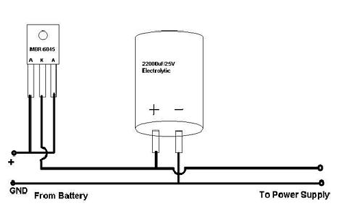
I got an email from casetronic confirming that the input is +12VDC +/- 5%. Yes, the C-134's power supply does indeed need a well regulated +12VDC power supply, as do, from the looks of it, all DC ATX power supplies. Do not hook these DC ATX power supplies directly up to your battery! It may work, but you seriously run the risk of shortening the lifespan of the computer (or worse). Over-voltage is not the same thing as "overclocking" (which I also do not subscribe to). Some over voltage is OK, but that "some" is already accounted for in their +/-5%. Your car will output [a noisy] 16V when running: I am sure you can do the math, but for the record that is a 33% increase in input voltage. Power this computer directly from you battery at your own risk: I for one am going to build or buy a 12V 5A regulator to protect my investment.
I have also found these other power supplies that all say or infer a
similar thing: Mini-Box PW60,
Lex,
Morex
This should be enough proof that all DC ATX power supplies should be run off
of a well regulated 12V power supply (unless they specifically say
otherwise).
FYI: The PW60's FAQ (written in March 03) says that in May or June 03 they
will be releasing a 9-18V to 12V power "inverter" with built in ignition
shutdown abilities. SWEET, but I cannot wait that long! :)
Then I find this link:
http://www.starfighter.org/karkomp/.
I don't care much for his actual PC or screen solutions, but it does have
an excellent
shutdown circuit!
The "original page" that he mentions can be found
here.
Since I still need a well regulated 9V power supply (for the Altinex video devices), I might as well experiment to see if I can make the KarKomp's circuit useful for my purposes. The difference will be that I will probably use a PT6656 regulator (9-28V in, 12V 5A out). The only problem (so far) that I can find with the PT6656 is that it is $27/chip!! (gasp). I am so close to completing this project with a minimal amount of "building", that I think it may be worth it to build a quality uber power regulator. I still cannot believe that I have a high quality solution to my "VGA to RGBS Switchbox" problem for only $50, and I didn't have to build a thing (except the wiring)! Ah, the parts ain't here yet, so the solution hasn't exactly been "realized" yet. Time will tell.
One thing I have learned though is that if I look long enough I tend to find a much better solution. Maybe I will stumble across a nice 9-18V to dual 12V/9V regulator with ignition startup/shutdown abilities! (yeah, right!)
Incidentally, I also found this very cool
1U +12VDC ATX power supply: 180 Watts?!?!?!?
This would have changed everything if I had seen it last month when I was
still trying to piece together a 14" deep 1U P4 rack server.
I don't really believe the 180W, but this is definitely worth investigating
if you are interested in building a 1U system in your car.
My next machine for a car might be a 1U! :)
2003/04/17
The Casetronic C-134 came in today and what a cool toy! It is a great little device. I installed the OS and most of the apps I need today. I took a look at the 12VDC to ATXDC power supply and I am a bit concerned that it might need a pre-regulated 12V (5A!) power supply in order to work correctly. I have emailed Casetronic for some more specifics about the power supply (I was hoping it it would have been mentioned in the box or manual...it wasn't). If the DC/DC converter cannot handle an unregulated supply then I will need to build a 11-16V input to 12V 5A output regulator. Looking at http://www.digikey.com, the part to best handle this job is PT6656. I will await for either a response to my email or a bit more investigation before I go ahead and build this simple circuit. If this circuit is necessary then the total power regulations I need from my car's 11-16V power source are:
- +5VDC (low power [1W?]): Used to drive logic gates
- +9VDC 1A (9W): Used to power both the DA1910SX (9V, 1W [max]) and DA1914SX (9V, 3W [max])
- +12VDC 5A (60W): Used to power the C-134 computer
Powered directly from the battery, but signaled on/off from the ignition- Ignition power goes from bad to good [and computer is turned off
(optional?)]
(this part of circuit may be able to be simplified if the computer is set to automatically turn on when it receives power)- Turn on battery power to computer
- Wait X seconds (recommend 5?)
- Trip the computer's power switch (turn on)
- Ignition power goes from good to bad *AND* computer is turned on
- Trip the computer's power switch (turn off)
- Wait Y seconds (recommend 60?)
- Turn off battery power to computer
- Ignition power goes from bad to good [and computer is turned off
(optional?)]
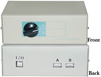
2003/04/16 - BREAKTHROUGH!
I discovered these two beauties!
Where have these been all of my life?!?!?! :)
I even found both of them on ebay for [hopefully] less than $100 total (I
will know in a few days)!
I have no hope of building devices with this much quality for that little
money.
As such, my quest for video signal conversion and switchbox is pretty much
complete...and without building a thing.
The only thing left is the 12V ignition sensing shutdown power supply.
Maybe I can find one of these devices too!
These Altinex devices are powered by 9V, so I will still need to build a regulated power supply, but +9VDC instead of +5VDC, and capable of handling 5.5 Watt load (611mA).
DigiKey is my friend! :)
2003/04/06
SUGGESTION: From my experience, when buying a new car, do NOT purchase the dealer's Navigation option. Typically a dealer NAV option will run you $2000+. The systems tend to be of low to moderate quality and most are proprietary or use proprietary cabling. A NAV unit is like any other computer; it will be obsolete in 18 months, so you are better off getting something that is upgradeable (in 2 years these things will have a frame rate and display quality at least equal to Quake). Aftermarket NAV systems are more upgradeable and customizable than dealer units. Some suggestions for NAV units are:
One of the better parts of using an aftermarket system is that you may not be limited to using RGB video signals. RGB is definitely the better signal, but you are only viewing a 7" display, and converting video signals can actually degrade the quality. Plus, a good video converter will cost well over $100.
Unfortunately, I was unwise and got the stock NAV system w/ my Z. The stock Nissan NAV screen uses RGBS video signals: 4 cable RGB + Composite Sync. Other RGB formats exist (3 cable RGsB [sync-on-G] and 5 cable RGBHV to name two), but they do not appear to be compatible with this screen (I am still experimenting). The rest of this article will focus on my efforts of working with an RGBS display. For more information than you ever cared to know about video format, go to MAXIM's (no, not the magazine) Understanding Analog Video Signals, MAXIM's Video Basics, and Video Signal Standards and Conversion Page.
Since my NAV display is RGBS, obviously my NAVCPU is too. To introduce a 2nd video source to the screen I essentially need an A/B Switchbox. Ideally the inputs would all be RGBS (so as to minimize conversions). So, there are two problems here.
- RGBS A/B Switchboxes do not appear to exist
(I cannot find anything small and portable for a reasonable cost)
I need to build an RGBS A/B Switchbox - The PC does not output RGBS (it outputs VGA, S-Video, and Composite
Video)
I need to build a VGA to RGBS converter (converting from low quality S-Video or Composite will only give a lower quality)
So, I have decided that it would be fun to build one circuit that both converts VGA to RGBS and allows me to toggle between two video sources. I will break this project into its two parts (building each circuit on breadboard) and then I will integrate them back again into the final result using a home made PC Board.